In visual computing class, we have studied visibility as rester approach, more specifically we looked up Hidden Surface Removal (HSR) algorithms, some examples of this algorithms are the Painter’s algorithm, binary space partitioning (BSP), Warnock algorithm, among others.
I was doing research about rasterization and I found something interesting about clipping. Clipping is a method to make or not rendering operations in some region. A rendering algorithm in clipping, only draws pixels in the intersection between the clip region and the scene model, lines and surfaces outside are removed. Clipping are used to improve render performance.
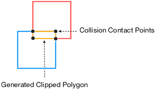
The Sutherland Hodgman algorithm is one of the most known algorithms used in clipping. To be precise, this is one of the polygon clipping algorithms and solves problems in other subjects. For example in physics, the collision detection whose goal is to report if two objects have collided, it used the GJK Algorithm but it doesn’t detect the contact points, in this case the Sutherland-Hodgman algorithm provides this information.
The Sutherland Hodgman algorithm.
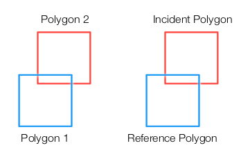
The algorithm begins by identifying a Reference and an Incident Polygon.
The segments of the Reference Polygon are used as Reference Planes. In the image, there are four reference planes.
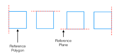
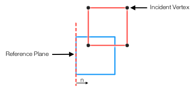
Then, the algorithm tests each vertex of the Incident Polygon against each reference plane.
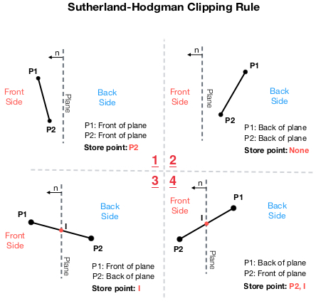
Sutherland-Hodgman Clipping Rule
This rule require the distance between a point and a plane, but we only need the sign of the distance. If the distance between a point and a plane is positive, the point is considered to be on the Front side of the plane, otherwise is on the Back side of the plane.
The rules are:
If points P1 and P2 are on the front side of the plane, the algorithm saves point P2.
If points P1 and P2 are on the back side of the plane, then none of the points are saved.
If P1 is on the front and P2 is on the back side of the plane, then compute an intersection point with the plane. The algorithm stores the intersection point.
If P2 is on the front and P1 is on the back side of the plane, then compute an intersection point with the plane. The algorithm stores point P2 and the intersection point.
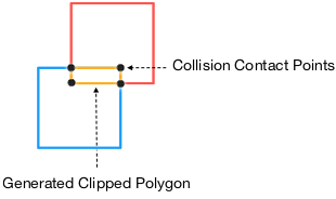
The algorithm finishes with a new polygon whose vertices are the contact points of two collided polygons.
Step by step algorithm.
Assume two boxes are overlapped. The first step is to identify the reference and the incident polygon.
For each reference plane, apply the Sutherland-Hodgman Clipping rule.
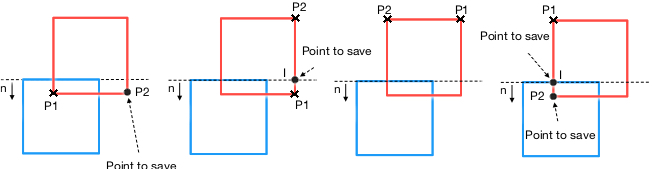
2a. Starting with the left plane (image below):
In the first instance, both points P1 and P2 are in front of the plane. Thus, P2 is saved.
In the second instance, both points P1 and P2 are in front of the plane. Thus, P2 is saved.
In the third instance, both points P1 and P2 are in front of the plane. Thus, P2 is saved.
Finally, both points P1 and P2 are in front of the plane. Thus, P2 is saved.
-
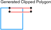
- The algorithm uses these collected points to generate a new polygon that is used as input for the next iteration.
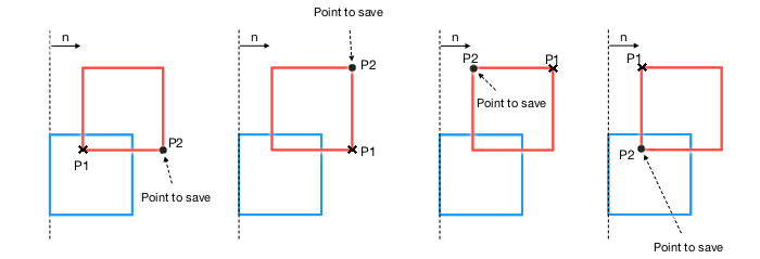
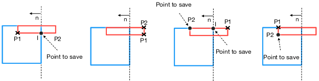
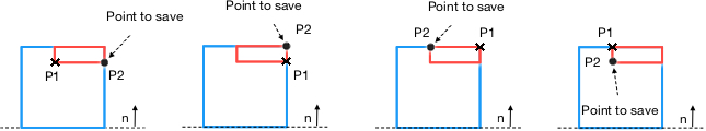
2b. Using the generated polygon and the next reference plane, apply the Sutherland-Hodgman Clipping rule again.
In the first instance, both P1 and P2 are in front of the plane. Thus, P2 is saved.
In the second case, P1 is in front of the plane, but P2 is on the back of the plane. so an intersection point with the plane is calculated and this point is saved.
In the third case, both P1 and P2 are on the back of the plane. Thus, none of these points are saved.
Finally, in the fourth example, P1 is on the back of the plane and P2 is in front of the plane. An intersection point is calculated. Both P2 and the intersection point are saved.
-
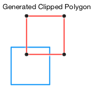
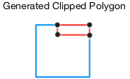
- We get a new polygon from these new points.
2c. Using the previous polygon, repeat the Sutherland-Hodgman algorithm to the right reference plane.
In the first instance, P1 is in front of the plane and P2 is on the back. Thus, an intersection point is calculated and saved.
In the second instance, no points are saved because both lie on the back of the plane.
In the third instance, P1 is on the back and P2 is in front of the plane. An intersection point is calculated and saved along with P2.
In the fourth instance, both P1 & P2 are in front of the plane. According to the rule, only P2 is saved.
-
- We get a new polygon.
2d. Repeat the process with the last reference plane.
- In every instance, the points lie in front of the plane. Thus, the four corresponding points, P2, are saved.
-
- We get the same polygon from the previous iteration.
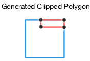
3 . The algorithm terminates generating a new polygon whose vertices represent the contact points of the collision.